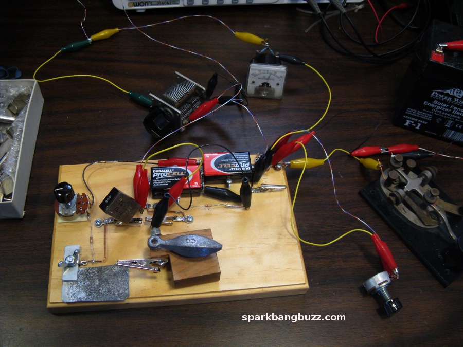
This project pictured above is like a crystal set in reverse - a 40 meter (7.035 mhz) CW transmitter instead of a receiver.
This 50 microwatt (.00005 watt) transmitter could easily be heard from a distance of 5 miles (straight line GPS distance).
The transmitting antenna was a 50 foot wire run through a hole in the wall and supported by a tree. The ground was a 33 feet 4 inch long wire run through a hole in the wall and laid on the ground.
I believe that many who may be interested, will find sufficient detail here to replicate this project.
Sending a radio signal 5 miles even with the low power of 50 microwatts is by no means extraordinary but it was very satisfying and fun to do it using a homemade semiconductor device - without the use of any manufactured tubes or transistors whatsoever. I suspect that much greater distances than 5 miles could be covered by sending from the right locations under the right conditions. I am not a low power fanatic. It is just that 50 microwatts at 40 meters is typical for what this rig can put out.
This project was also done successfully a few years ago on 80 meters (3.579 mhz) ( Zinc negative resistance 80 meter CW transmitter) but being able to do it on 40 meters (7.038 mhz) brings an even higher level of satisfaction.
The power output from this transmitter is less than what my DX-40 transmitter puts out in the tuning mode (final amp turned off).
Even though this transmitter is simple, skill and patience is required for its tuning and use but the fun and satisfaction this project offers makes all the effort worthwhile. Traditional oscillator circuits using a transistor, crystal, and a couple of resistors and capacitors, offer a much easier way to send a CW signal a few miles. The Easy Ten transmitter described elsewhere on this web site is a good example.

The zinc 40 meter CW transmitter pictured above was located in the small town below and could be heard at this 5 mile distant location up the mountain using a hand held HF receiver with a BFO and telescoping 3 foot antenna.
Actual sound of 40 meter transmitter recorded at 5 mile distance.Transmitter is being keyed at a rate of approximately once per second.
The heart of this transmitter is the zinc negative resistance device (ZNR in the schematic below). It is the closest thing there is to a homemade transistor using household materials from scratch. Even though it is a two terminal device, I have made numerous circuit projects that work the same as though they were made with a factory made transistor. Some of the projects include a negative resistance driven LED strobe light, audio oscillators, tuning fork driver, crystal set amplifier, sound synthesizer and more.
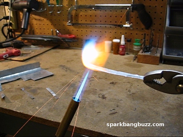
The zinc negative resistance device is easily made by putting a piece of galvanized sheet metal into a propane flame until it gets red hot and flares up with a bright white flame and sparks. This seems to produce good negative resistance material. With a propane flame it is difficult to get a big area of sheet metal hot enough to flare up well so I often cut strips about 1/4 to 3/8 inch wide before putting them into the flame. I recently made some very big pieces of galvanized sheet metal flare up very well with an acetylene torch. This is best done outside since torching galvanized metal is known to produce poisonous fumes.
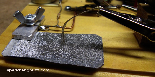
After cooling, the metal will be covered with white zinc oxide and many black spots of what I believe to be zinc ferrite. These black spots are the negative resistance areas that make this transmitter work. A fine wire catwhisker is moved around on this surface until a good oscillating spot is found - just like adjusting a crystal set.
After making projects like this now for more than a decade, I find the flame treated galvanized sheet metal to be the best negative resistance material I have ever used. It is much superior in consistency, repeatability and adjustability than all other materials I have tried, including iron pyrite and the zincite samples that I have acquired. When using the zinc device, I can almost always hear some form of oscillation in the receiver after just a few seconds of catwhisker adjustment. Good powerful and stable catwhisker settings usually take a bit longer however.
Typical curve of zinc negative resistance device. Horizontal represents voltage and vertical represents current.
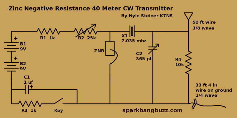
Schematic of zinc negative resistance CW transmitter shown above.
ZNR is the zinc negative resistance device. It seems to be easier to get good catwhisker settings when the piece of heat treated zinc sheet metal is biased positive in relation to the catwhisker. I also find it helpful to use a small bundle of fine wires instead of just one fine wire for the catwhisker.
When a good spot is found with the catwhisker, a CW signal will be heard on a nearby receiver tuned to the crystal frequency. Adjustment of C2 (365pf variable capacitor) will optimize the signal coupling to the antenna. Best results are obtained by adjusting C2 and R2 (25k pot) together for optimum power output and oscillation reliability. See tuning meter below.
The 10k resistor R4 provides a DC path between the antenna and ground. This prevents electrostatic charge buildup and discharge which can destroy the catwhisker setting.
C1 and R3 greatly improve the keying reliability of the transmitter. Without them, there are many catwhisker settings that stop working after opening and closing the key. Almost all catwhisker settings seem to key well when C1 and R3 are in the circuit.
The pot in the foreground (top picture above) is not shown in the schematic. It is a 25k pot placed in parallel with the key to reduce chirp. This pot will reduce keying chirp if it's resistance is set just high enough for the circuit to stop oscillating when the key is up. This reduces the differences in power dissipation across the zinc device, when keying.
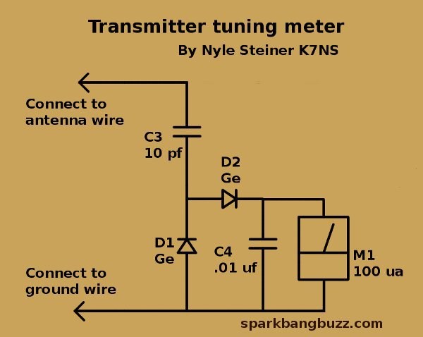
This meter circuit was drawn separately from the transmitter circuit for clarity. It is connected between the antenna and ground wire.
I call this a tuning meter because it is neither an SWR meter nor a power meter. It simply shows relative voltage signal level across the antenna-ground feed point. The objective is to get the highest reading possible consistent with good signal stability and keying reliability while making adjustments to the zinc negative resistance device, R2 and C2. Various transmitter adjustments will usually produce readings between 5 and 50 microamps.
I also like to call this meter a "Bottom Line Meter" because after all that may be accomplished by using a fancy SWR meter and power meter, the bottom line is that maximum signal voltage represents maximum power to the antenna. It just doesn't tell you how much. To get some idea of the output power, I used other means as described below.
AS LONG AS THE FREQUENCY AND THE ANTENNA-GROUND SYSTEM REMAIN THE SAME, A PEAK READING ON THIS METER WILL INDICATE MAXIMUM SIGNAL STRENGTH BEING FED TO THE ANTENNA.
The meter was reading approx 30 ua when the recorded signal was heard at a distance of 5 miles.
I almost always get good results using this "Bottom Line" method of tuning antennas. During one period of time, I was able to consistently make at least one contact a day across the pacific ocean from Los Angeles using roughly 1/2 of a watt.
This antenna-ground system and tuning method may not win any efficiency contest but I think I can safely say that it works reasonably well.

The antenna is 50 feet of wire supported by a loop of rope in a tree. This is 3/8 wave at the 7.038 frequency that is used here. I chose the 3/8 wave length antenna simply because it is a happy medium between the low impedance of a 1/4 wave and very high impedance of a 1/2 wave wire. I figured it would be a reasonable impedance to match to a transmitter.
The ground for the transmitter is a 1/4 wave 33 feet 4 inches long wire laid on the ground. Alternatively, clipping to the screw of an electrical outlet inside the house seems to work just about as well for a transmitting ground. I was interested however, to see how well the quarter wave ground wire would work for reasons of portability and the ability to set up an antenna system in the field away from house grounds etc. The quarter wave ground wire seems to work well in comparison to other types of ground connections.
Almost any antenna length can be loaded up to transmit well but I am describing this exact configuration including the wire laid on the ground, because it seems to work well enough and it makes all the variables repeatable for anyone who may be interested in replicating this project.
When I used this transmitter on 80 meters everything was done exactly the same way except for using a 98 foot antenna wire, a 65 feet 4 inch ground wire and a 3.579 mhz crystal.
The tuning meter described above and C2 of the transmitter seemed to work well for matching and loading up this antenna. No fancy SWR meters, power meters or transmission lines were used. It would be difficult to find equipment that could give accurate readings at such low power levels anyway.
Being curious about output power levels however, I made some effort to determine the approximate power obtained from the output of the transmitter.
I improvised an impedance bridge to measure the feed impedance of this antenna and ground system. The results of my crude antenna measurements were 300 ohms resistance and 568 ohms inductive reactance at the frequency of 7.038 mhz. Some elementary trigonometry revealed an overall impedance of 642 ohms. I used these values to help determine how much power this transmitter was putting into the antenna.
While doing some previous testing with an oscilloscope connected between antenna and ground, I found that a healthy catwhisker setting could produce roughly 800 mv peak to peak or more. 800 millivolts peak to peak causes about 30 microamps deflection of the meter described above. The meter, connected between the antenna and ground, read approximately 30 microamps when the 5 mile transmission was heard.
800 mv peak to peak is equivalent to 283 mv rms. Dividing this by 642 ohms gives 440 microamps. 440 microamps squared times 300 ohms resistance gives 58.2 microwatts output.
As an independent test, I connected the output of the transmitter to a 300 ohm resistor and an oscilloscope. Some of the scope readings were 350 mv peak to peak across the 300 ohm resistor. 350 mv peak to peak is equivalent to 124 mv rms. 124 mv squared and divided by 300 ohms gives 51 microwatts. These two tests agree close enough that I am satisfied that the transmitter was putting out very roughly 50 microwatts.
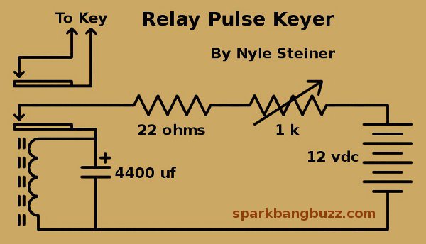
This circuit keys the transmitter about once every second to make the signal easy to identify. This type of keyer made it possible to do the experiment, including keying the transmitter, without having any transistors whatsoever in the entire transmitting system.
It is a relay connected as a buzzer but with a huge capacitor across the coil to make it run slow (about one pulse per second). The 1k pot can adjust the duty cycle to approx 20 to 40 percent. In this case a 4400 uf capacitor is used but the size of this capacitor has to be determined by experiment depending on the relay used.
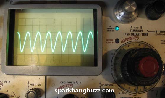
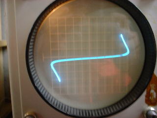
Zinc negative resistance crystal oscillator running at 7.038 mhz. The scope trace clearly shows that the circuit is running at a true 7.038 mhz. and not at some sub multiple frequency.