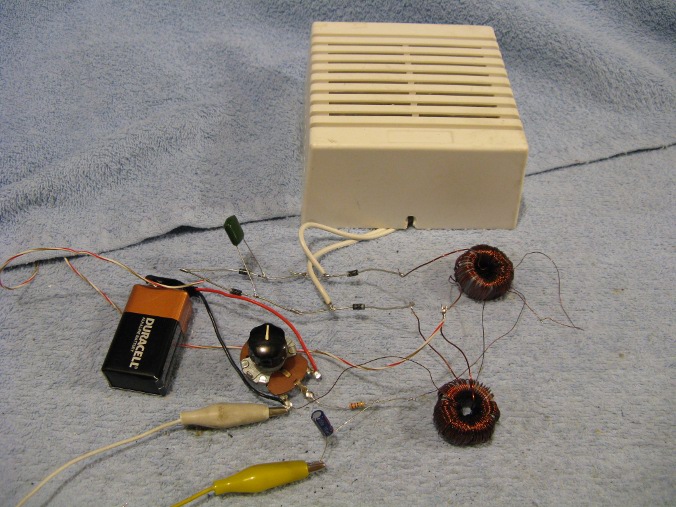
A magnetic audio amplifier. The 9 volt battery is to supply dc bias to the circuit.

Magnetic audio amplifier schematic.
High impedance signals can be fed into the input of this circuit by using a matching step down transformer such as the Bogen T725 or similar. It is sometimes helpful to bypass the output of the transformer with a .1 uf capacitor and run the signal to the input through an inductor of several millihenries to keep any residual 35 khz signal from feeding back through the input to the crystal set.
A typical crystal set connection with the T725 would be to groud the black wire, connect the brown wire to the input of the magnetic amplifier and the purple wire to the crystal set output.
This is my second report on magnetic amplifiers. The first was a description of how to control the brightness of an incandescent light powered by 12 vac. See: Homemade Magnetic Amplifiers using common 12 Volt Transformers. This report shows how I applied the same principle, using toroids and a 35 khz ac power source, to make a magnetic audio amplifier.
The purpose of this project was to see if I could make a working audio magnetic amplifier using common materials. This amplifier works very well under the circumstances that the toroids were randomly chosen surplus aquisitions from my parts box. Using the speaker as a comparison between the input signal and the output signal, the signal is very much louder at the amplifier output.
Using this amplifier to control the brightness of a car tail light instead of an audio amplifier, I found the gain to be quite high. With not very careful measurements, the power gain appeared to be well over 2000. I will update this if I can make more accurate power gain observations. In any case there is definitely some noteworthy gain.
To evaluate the amount of gain using the tail light, I compared the change of input power with the change of output power dissipated by the output load. In other words, I multiplied the change of output voltage across the load times the change of current through the load. I then divided this by the change of input voltage times the change of input current.
The source of ac power for this amplifier was a quickly made 35 khz oscillator that puts out a 10 - 12 vac sine wave capable of lighting a car tail light to full brilliance. This oscillator is not yet designed well enough to publish here.
It is interesting to note that with the magnetic amplifier using diodes and 60 hz to control a car headlight, the light is quite bright with no input dc bias. Applying a dc bias to the input, depending on its polarity, will turn the light either dimmer or brighter. See: Homemade Magnetic Amplifiers using common 12 Volt Transformers. In this circuit, using 35 khz and toroids to control a light, the light is completely off with no input dc bias. A positive dc bias will turn the light on and brighter. This is why the input coil polarity dots are on the bottom instead of on top as shown in the car headlight control circuit. This suggests to me that these toroids may be capable of controlling a lot more power than is being controlled in this experiment.
The mag amp is true amplification without the use of tubes, transistors or IC's but it does require the use of an ac power source. While most ac oscillators require the use of transistors, this amp could concievably run using an ac power signal from a carbon arc or maybe even a zinc oscillator or similar.
There are some good articles online about magnetic amplifier theory. Two of the best are: The Transformer Book by Lee Reuben and Magnetic Amplifiers by Mali. They can be found on google. Most of these articles however, describe mag amps in theoretical terms. They can easily lead one to think that special cores and transformers would be necessary in order to to actually build a magnetic amplifier. Nothing could be farther from the truth.