
I am guessing that the natural zinc oxide layer that forms on the wire may be responsible for the negative resistance of the device described here. The voltage level where the negative resistance happens is fairly consistant and is almost always between 200 and 250 millivolts. The current level where it happens however, can vary widely between 20 and 100 milliamps.
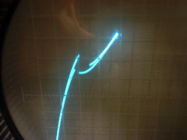
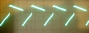
This circuit can be easily powered from a 1.5 volt battery. One characteristic of N type negative resistance devices is that they typically require a very low bias source resistance in order to keep the bias voltage stable within the negative resistance region. With too high of bias resistance, the voltage, as it enters the negative resistance region, will have a tendacy to suddenly jump past it. This is why a gap is seen in the curve (see photo). This homemade device, with its narrow negative resistance region, requires an even lower bias source resistance than a typical tunnel diode. A typical tunnel diode can be biased within the negative resistance region with a bias resistance of around 20 ohms. This device works best when the bias resistance is 1 ohm or less. Unlike this N type device, S type negative resistance devices, such as the heat treated galvanized sheet metal device, act in the opposite way and bias stability is best with a higher bias source resistance.
This device, like many others that I have been making, has a symmetrical curve in both the positive and negative direction and can work with the battery connected either way. Just for the sake of being consistant, I did most experimenting with the aluminum biased positive with respect to the zinc covered wire.
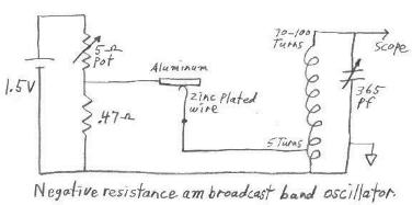
The low (approx 250 millivolt) bias voltage for this device was produced across a .47 ohm resistor, connected to the battery through a 5 ohm pot. This means drawing 500 to 600 milliamps from a 1 1/2 volt battery in order to supply approx 35 ma to the device. A 5 ohm pot is not as common as a 50 k ohm pot but can be easily obtained at a surplus outlet. It might also be easy to improvise a 5 ohm pot from something like a pencil lead. It was easy to run the circuit from a single AA cell but of course a D cell is much more suitable when drawing this much current. An emitter follower circuit could be a much more efficient way to bias this device but I like to have this circuit completely void of any commercially made transistors or other active devices. I wanted to be absolutely sure, that this homemade device is indeed what is actually producing the oscillations. Below are schematics and waveform pictures of an LC oscillator and a relaxation oscillator.
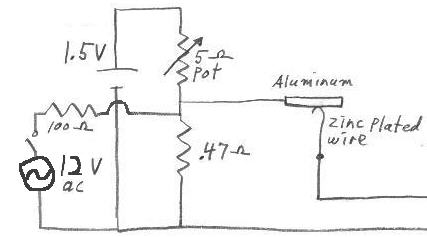
A curve tracer is not always a handy thing to have around. The circuit can also be easily adjusted by using just an oscilloscope and a 12 volt transformer, as shown in the partial diagram below. While the normal dc bias is applied and adjusted to approx 200 to 250 millivolts across the .47 ohm resistor, 12 volts ac from a transformer can be switched into the circuit through a 100 to 200 ohm resistor. This applies a varying dc bias to the negative resistance device. The catwhisker can then be adjusted until you see 60 cycle bursts of rf on the scope. If the ac voltage is now switched off, a continuous oscillation can usually be achieved by watching the oscilloscope and adjusting the bias pot. The circuit will then be running entirely from the 1-1/2 volt battery.
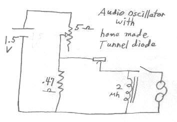
The audio frequency oscillator can be easily adjusted without an oscilloscope or curve tracer by simply connecting a pair of headphones across the inductor. The temporary application of the 12 volts is still helpful.
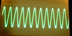
So far, it is easy to get a continuous sine wave signal at 1 mhz. The amplitude of the oscillation is typically between .35 to 1 volt pp. Few things can beat hearing a hetrodyne on a radio receiver that is the result of a homemade active device.
With the am broadcast band LC circuit, the signal is usually a nice looking sine wave with the frequency being adjustable across most of the am broadcast band by turning the variable 365 pf capacitor. The coil is 100 turns of .034 dia. enamel covered copper wire on a piece of 1-1/2" abs pipe (1-7/8" outer diameter). Taps were placed at 5, 10, 15, 20, 25, 30, 40, 50, 60, 70, 80, and 90 turns. As shown in the diagram, the very low impedance of the device worked best into the 5 turn tap. The variable capacitor was connected to between 70 and the full 100 turns of the coil.
In trying to produce higher frequencies of the order of 7 mhz, I substituted an LC circuit with a smaller inductance coil. While using this higher frequency LC circuit, the long sloppy clip leads used to build the circuit, were a much greater factor in determining the frequency than the LC circuit was. By taking the LC circuit out and substituting it with just varous sized inductors or even just pieces of wire, in series with the negative resistance device, a relaxation oscillator was made. This relaxation oscillator could be made to run anywhere from audio frequencies to (with careful coaxing) 12 mhz, depending on the size of the inductance in the circuit. The higher frequencies were produced just by putting various lengths of the wire in series with the device.
The only limitation on the lowest frequencies attainable with this relaxation oscillator, seems to be the internal resistance of the inductor. Big inductors tend to use more wire and thus have a higher resistance. With this circuit requiring such a low bias resistance, one ohm is close to the maximum internal resistance that is usable in an inductor. The inductor for audio frequencies should therefore be made with as few turns as possible and as large diameter of wire possible into a toroid core with a high permeability. A typical inductance for attaining audio frequencies with the above relaxation oscillator, is 2 mh.
The negative resistance part of the curve can form at many different current levels. With the relaxation oscillator, negative resistance at higher current levels seemed to produce lower frequencies. This is probably because the overall resistance across the inductor, is lower when the negative resistance is at a higher current level.
Several different pieces of zinc from different sources, in addition to the galvanized wire, were tried and they all seemed to work for making the negative resistance. I also had success using different pieces of aluminum from different sources. None of the pieces of aluminum were anodized. I was even able to get the circuit to work after buffing the aluminum and galvanized wire with a piece of "Scotchbright" like material. No special treatment or heating needed to be done to either the zinc or aluminum. The aluminum and the galvanized steel wire were used in their original condition.
