I call this very simple transmitter the "Easy Ten" because it can be easily heard at a distance of 10 miles. Transmitter antenna is a random length wire run through a hole in the wall and thrown into a tree.
The white wire just visible in the upper left is the antenna. The Red clip lead that exits at the upper right is a ground wire connected to the ground screw of an electrical outlet.

Looking toward the transmitter location in a small town that can barely be seen 11.5 miles away. The transmitter could be heard clearly from this location, the top of a hill overlooking a lava field.

I am not an antenna fanatic and I like to work with the simple stuff, especially when it comes to working with frequencies in the 3.5 and 7 mhz range. Fussing around with coax lines, SWR, baluns and all that fancy stuff does not usually appeal much to me, nor have I found it at all necessary for getting a signal out. A simple random length of wire thrown into a tree works very well if you can simply adjust the transmitter to put a signal into it.
I certainly am not trying to say this is the best way to make antennas. The point that I wish to emphasize is that the simple techniques that I am describing here, do work well and make good respectable antennas. I have made many many contacts across the pacific ocean and across the United States using simple antennas as described here and just one watt of output power. I have almost always been able to make contacts with stations at least two states away from any given antenna setup using just one watt.
A simple homemade level meter can tell you when you have optimized the signal output to the antenna. The signal meter is capacitively coupled to the antenna and reads it's RF voltage level. A signal level meter can be easily made from a DC microameter and a germanium diode. Connect the germanium diode across the meter with the cathode on the positive side. Then connect one side of the meter to ground and the other side of the meter to a short wire (one or two feet long) that rests near the antenna wire from the transmitter. It does not matter which side of the meter goes where.
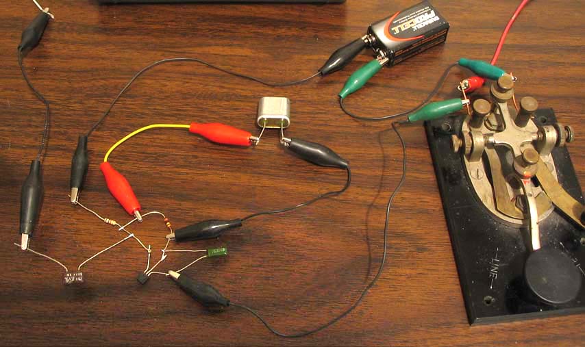
With the key down, adjust the 365 pf variable capacitor in the circuit above for a peak reading on the meter. That is all there is to it. With the circuit described above, a big antenna will tend to swamp the oscillator and prevent it from running. The variable capacitor attains the best compromise between swamping the oscillator and having too little of antenna coupling. The picture above shows a fixed capacitor feeding the antenna. A variable capacitor was first used to peak the signal meter and then an equivalent fixed value capacitor was put in it's place. A capacitor is not necessary at all sometimes with shorter antennas. In this case the antenna can be connected directly to the transistor collector.
This simple meter has worked well on numerous other transmitter projects. This meter can not tell how much power a transmitter is putting out but it is very good for indicating when the transmitter is putting the most signal into the antenna. For a given transmitter, you don't really need to know how much power it is putting out. You just need to know when the transmitter is putting what it is capable of into the antenna. This meter seems to accomplish that.
With all other conditions remaining the same, the more signal voltage there is on the antenna, the more power the antenna is radiating. It is that simple. Don't worry about near field and far field theory or any of that stuff. According to theory that I have read, you can not have a near field without having the far (radiating) field.
There is a basic rule about loading an antenna with this signal level meter. The indications from the meter are valid as long as changes or adjustments are made between the meter and anywhere in the transmitter. The meter indications may not be valid for any changes made beyond the meter (farther out the antenna or ground lead).
When you want an idea of how much power the transmitter can put out, it is easy to substitute dummy load resistors at different values in place of the antenna. The peak to peak voltage across the resistor read by an oscilloscope, can then be divided by two and multiplied by .707 to get the rms value. This value when squared and divided by the resistor value will give the power being fed to the resistor according to ohms law. I am usually curious about the values obtained using 50 to 220 ohm resistors.
It appears that the simple circuit shown above can work well into a wide variety of load values without using any additional load matching components. Using a 9v battery I measured the transmitter RF output power into several dummy load resistors as described in the previous paragraph. The result was in the range of about 5 to 7 milliwatts. They are listed below.
56 ohms 1.5v pp 5.02 milliwatts
150 ohms 3v pp 7.49 milliwatts
220 ohms 3.5v pp 6.96 milliwatts
510 ohms 5v pp 6.1 milliwatts
I was also able to run this transmitter on 3 volts but the power output was much lower - in the range of 300 to 400 microwatts. These microwatt levels could still be heard (not as strong) several miles away.
The circuit above is far from a representation of the amount of RF power output that can be supplied from a single transistor circuit. The main purpose of this project was to get an idea of what can be accomplished by simply coupling an antenna to a simple oscillator circuit.
It seems that the biggest disadvantage to all this simplicity is the difficulty in knowing exactly how much power is going up the antenna. Getting optimum power up the antenna is not nearly as difficult and is the main concept presented here. The dummy load resistors tell how much power can be put out with different loads but the exact load these random length antennas present to the transmitter is a bit more difficult to determine. These questions can be answered by delving into more sophisticated practices.